

How is the technical data of our signaling devices created?
Depending on the requirements and the field of application of a signaling device, the technical data is the information you need to decide on the right signaling device. But how is the data actually created and what does it mean?
What are the technical data?
In addition to the technical data, which is specified using certain material or components, there are also data that specifically describe the finished product, our signaling devices. This includes, for example, type of light and luminous intensity or tone type & volume, but also the operating temperature, impact resistance and protection class. We will give you insights into the different test and inspection procedures and show you how this data is created.
Where does the technical data originate?
The data is created directly at Auer Signal in our research and development department. Our colleagues in the development department not only plan and design our signaling devices, but also test and inspect them. We have our own in-house testing and inspection facilities for this purpose.
How are the test values verified and certified?
Auer Signal is part of the "UL Client Data Test Program". This means that Auer Signal can perform certain UL-relevant tests directly in its own test lab.

The results are strictly documented according to UL's guidelines and submitted to UL. The transmitted data is reviewed by UL before it can be used for certification. To be part of the "UL Client Data Test Program", one has to meet certain requirements - not only the company, but also the test equipment itself, which are calibrated annually to ensure the guidelines of accuracy and precision.
More information on the UL Client Data Test Program can be found here.
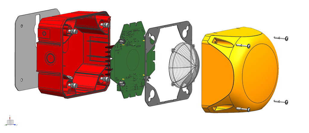
Development and testing of signaling devices
When developing new PCBs, our colleagues already have some idea of which circuit components and assemblies can be used. These PCB designs are tested on prototypes and partly simulated in advance on the computer with a design program.
The resulting circuit diagrams or schematics are like maps for our electronics engineers to read - which show how the device should function and how the individual components must be arranged to obtain the desired function in a particularly effective and innovative way. Gerber files are created from this layout in the next step.
With the help of the Gerber files (data format for exchanging data between development and production) of the newly developed PCB created by the technicians, usually five to ten PCB tests are created. These are directly assembled by our developers and afterwards dimensioned. This means that the individual component values are checked.
Electronic testing at Auer Signal
Our quality standards for the products we design and develop are particularly high, which is why we use every opportunity to make our products even more innovative and effective. Therefore, the electronic tests are always done with the sample PCBs in the first step. Only when our electronic engineers are certain that the PCB is optimally assembled, a small series is produced.
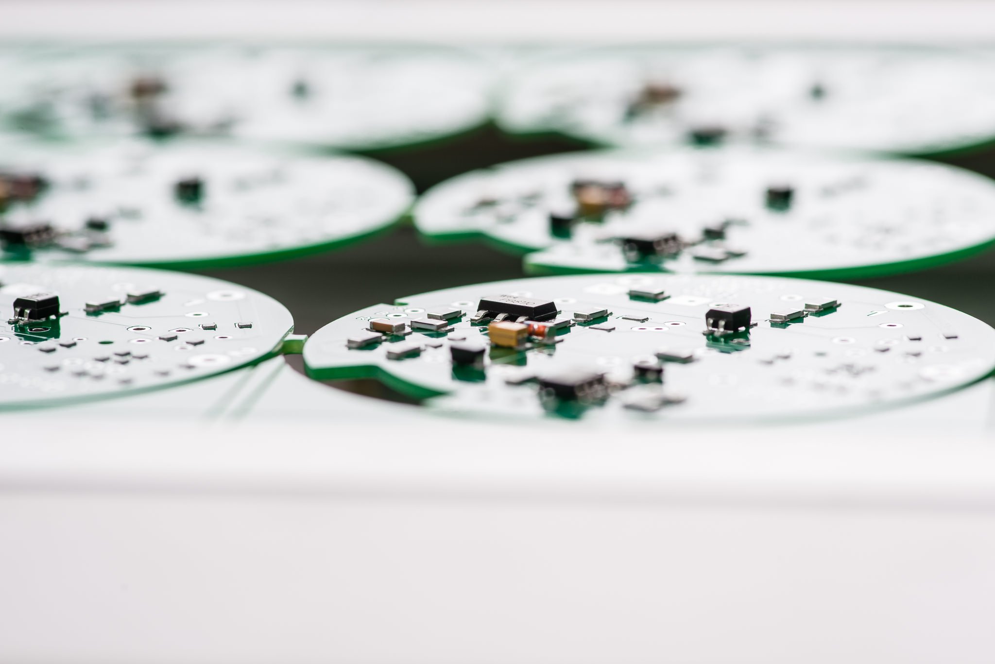
With the first small series from our production completed, tests are repeated via multimeter and oscilloscopes to validate the values. In addition, further tests are performed with the small series signal devices to determine, for example, luminous intensity and/ or sound pressure, weight, protection class, impact resistance, etc.
VOLTAGE VALUES OVER A PERIOD OF TIME
The oscilloscope is used to graphically display the voltage values over a defined period of time. Besides the multimeter, the use of the oscilloscope is the most important measuring instrument at Auer Signal for the dimensioning of the PCBs.
LIGHT INTENSITY BY SPECTROMETER
In order to determine the light intensity, the device is fixed to a goniometer. The goniometer can then freely move the device in the room, so that the luminous intensity can be measured in all directions. The luminous intensity is measured with a spectrometer, which can record all values relevant to light. A light measurement takes up to 2 days, depending on the resolution. The values are read out, graphically displayed and logged.
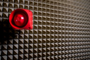
SOUND PRESSURE MEASURING
The sound measurement takes place in our own, anechoic sound measurement room. Depending on the design of the signal transmitter, the sound pressure is measured either from the front or from above. Key for the positioning of the sound level meter is the sound outlet opening and the usual mounting format of the signaling device. At a distance of 1m, the sound pressure is measured and recorded for one to two seconds.
OPERATING TEMPERATURE BY THERMAL IMAGING CAMERA
The thermal imaging camera is aligned directly above the circuit board. The signal device is switched on and after approx. one hour the operating temperature is checked and documented by the thermal imaging camera. One recognizes possible hotspots at a glance and can react faster than with individual measurements. If a component or a circuit component emits too much heat, the PCB is reworked and goes through all tests again. Thermal images of the PCB are created at an early stage in order to minimize the effort required for the subsequent heating test, since possible hotspots have already been identified and eliminated beforehand.
EMC-PRECOMPLIANCE TESTS
Auer Signals development department has a well-equipped EMC laboratory to perform EMC tests of various kinds during development. This shortens the development time considerably since the conformity is already checked in the development phase and the later conformity measurement at an external accredited laboratory can be passed at the first attempt.
Verification of mechanical properties
Products from the first small series are tested and verified in our specially created test laboratories. The documented data is verified by UL. At the customer's request, the products may also be checked regularly, for example at annual intervals. Also, if changes or improvements are made to the product, it will be rechecked and approved.
IMPACT RESISTANCE IKx / UL 746 C BY IMPACT TEST
In the impact test, a standardized weight is dropped onto the product from a defined height. This test is repeated at various points on the device. The housing must not be damaged to such an extent that the electronic components are exposed or damage is caused, as a result of which its function or water-tightness is no longer guaranteed.
For UL certification "UL 746 C - Standard for Safety of Polymeric Materials - Use in Electrical Context", the signal device is cooled to -35°C for at least three hours and then attached to a fixed structure. A 0.535 kg ball is dropped onto the cooled product from a distance of 1.296 m.
For the IKx impact test, the product is not cooled. For the IK08 impact test, a 2kg weight is dropped onto the product from a distance of 25cm. For IK09, it is a 5kg weight from a distance of 20cm.
The results of the impact test are documented and sent to UL for review.
OPERATING TEMPERATURE BY CLIMATIC CABINET
Our products are used worldwide under different weather conditions and must therefore withstand variable temperatures, humidity and influences. The test cabinet simulates these environmental influences.
Temperatures between -40°C and +190°C can be selected on the climatic cabinet used. The relative humidity can be set between 0% and 100% for tests.
By default, the following tests are performed in the climatic cabinet:
- Continuous operation at the upper limit temperature of the device for at least one week
- Operation for one week at the lower limit temperature of the device, here the function is checked variably
- as well as changing climatic conditions as defined in IEC/EN60086-2.
Additional climatic tests can be performed at the customer's request. More demanding climatic tests, such as thermal shock tests, are carried out by a local partner in an accredited laboratory.
The climatic cabinet, like all measuring equipment, is calibrated annually. The verification is not only an essential part of the UL Client Data Program but also of ISO 9001.
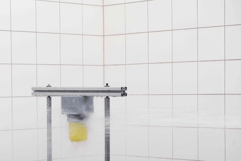
LEAK TEST IN THE WET TEST ROOM
For the leak test, the product is mounted on a rotating device, which rotates at a predetermined speed, depending on the diameter or circumference of the product. Four different types of protection can be tested in our wet test room:
- UL (UL Type 4)
- IPx7 (Dive test)
- IPx6
- IPx5
For this purpose, the wet test room is equipped with standardized water hoses and a dip tank in addition to the turning device. The flow meter indicates how many liters of water per minute flow through the hose and is calibrated annually.
Sequence of leakage test for the different standards:
UL Type 4: Nozzle diameter: 25mm, flow rate: 240l/ minute, distance: 3-3.5m, with a velocity at the junction of 6mm/s, test time: 3 minutes.
IPx7: Submerge under water for 30 minutes, at a depth of 1m
IPx6: Nozzle diameter: 12.5mm, flow rate: 100l/ minute, distance: 2.5 -3m, test time: 1 min/m² but min. 3 minute
IPx5: Can also be performed. However, by default, our products are tested to IPx6.
The result is either "Pass" or "Fail" and is logged with photos. All tests performed at Auer Signal are carried out and recorded exclusively by trained personnel.
Where can I find the technical data?
The technical data can be found on our website, in the catalogs, product folders and assembly instructions. For a more detailed explanation of the technical information, take a look at our technical information overview.
You can find the currently valid certificates in the download section. If you are missing a technical date, our Customer Service Team and Technical Support Team will be happy to assist you at any time.
